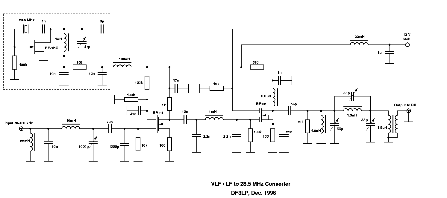
The design is comparable to those VHF converters described in many articles and the ARRL Handbook. It consists of four stages:
1. The crystal oscillator.
28.5 MHz was chosen since I used it with an old CW receiver who had
a fixed filter only for lower sideband. Tuning it to 28.4 MHz -100
kHz below the LO frequency- upper sideband is available.
The oscillator runs as a simple Pierce for overtone crystals. I'm using
a Amidon toroid (T37-6, yellow) for the 1uH coil. Adjust the 47p ceramic
trimmer for minimum drain current, minimum voltage over the 150 Ohms resistor.
2. The front end.
The 22mH choke prevents the amplifier from static and main line noise.
The input pi-filter coil is a high quality pot core and frequency tuning
of this preselector is very sharp. Use a high quality variable air capacitor
for the 1000pF. Tuning range here is from approx. 50 to 164 kHz. Adding
some nF in parallel lowers the input range. I used 7nF to receive the historical
transmission from SAQ (Sweden) in Aug, 1998 at 17 kHz.
The BF981 preamplifier stage provides approx. 20dB of gain. Running tuned loop antennas or ferrite rods this gain is absolutely necessary since those antennas have a "gain" of approx. -60dB over a dipole. For tuned longwires or verticals this stage would have a little bit too much gain but I never observed any cross- or intermodulation even using a 120m kite elevated wire for LF. This is due to the very selective front end.
Coupling to the following mixer stage is via an ordinary pi-filter preventing the mixer from breakthrough of LF and MF broadcasting stations.
3. Mixer stage.
This design is well-known from SW or VHF. The only difference is Gate
2 being run at 0 Volts instead of 1-2 Volts as usual. I found this to be
of better performance on LF.
4. Output circuit.
One major problem using 28.5 Mhz as output frequency with unbalanced
mixer stages is the high LO-level at the output. This often leads to an
overload of the following receiver. So some filtering effort is absolutely
necessary. The three coils are wound over T37-2 toroids from Amidon (red).
Adjusting the three ceramic trimmers is a bit tricky. Do not adjust
for maximum output! Tune the trimmers alternately for minimum carrier at
28.5 MHz (mainly the mid trimmer) and maximum output at 137 kHz (28.637
MHz on receiver). The output coupling consists of only two windings over
the 1.5 uH coil.
Using a good quality stabilized power supply is very important for stability of the output frequencies! If you have problems with LO overload use 14 MHz or lower ranges for crystal frequency and output range.
The Schematic: